This tab appears on the interface data dialogs of the following operations:
The following table shows a brief description of the variables appearing in this tab. The table also displays their default values and their generally acceptable range:
|
Variable |
Default Value |
Range |
|
|
||
|
○ Volatile ? |
<No> |
Yes/No |
|
◙ Evaporation (%) |
0.0 |
0-100 |
|
● LOD Before Evaporation (%) |
0.0 |
0-100 |
|
○ LOD After Evaporation (%) |
5.0 |
0-100 |
|
● (Heating or Cooling) Gas Out Dew Point (°C) |
25.0 |
Positive |
|
○ Entrainment (% of Dried Material) |
0.0 |
0-100 |
|
● (Heating or Cooling) Gas In Gas Stream |
<None> |
Dedicated Input Port |
|
◙ Relative Amount of (Heating or Cooling) Gas In Stream (wt Gas/wt Evaporation) |
8.0 |
Positive |
|
◙ Volatile Content of (Heating or Cooling) Gas Out stream (wt Volatiles/wt Non-Volatiles) |
0.02 |
Positive |
|
◙ (Heating or Cooling) Gas Out Temperature (°C) |
70.0 or 25.0 |
Positive |
|
◙ (Hot or Cold) Product Temperature (C) |
70.0 or 25.0 |
Positive |
Symbol Key: ○ User-specified value (always input); ● Calculated value (always output); ◙ Sometimes input, sometimes output
Specification Choices / Comments
The following list describes the available specification choices in this tab; for more details on how these are implemented, see Rotary Drying: Modeling Calculations.
•Volatile ?...
All volatile components that are removed (evaporated) during drying must be identified as such.
•Volatile Component Evaporation...
If the evaporation of volatile components is calculated by the program based on LOD After Evaporation, then it is assumed that all volatile components have the same evaporation %. If that is not the case, then you need to set the evaporation percentage of the various volatile components.
•View/Edit Composition Button for (Heating or Cooling) Gas In Stream...
Click on this button to specify the composition of the (heating or cooling) gas inlet stream (mid- or bottom- inlet stream, respectively). The actual flow rate of that stream will be adjusted based on the selected flow specification option for that stream during simulation.
•Heating Gas In/Cooling Gas In Stream Flow Specification Options...
You may choose among four different options for specifying the inlet drying gas (“Heating Gas In” or “Cooling Gas In”) stream’s flow requirement: you can specify the inlet gas stream’s flow directly (though that stream’s data dialog) or you can specify the relative amount of the inlet gas stream (ratio of inlet gas mass flow rate to total evaporation rate) or the volatile content of the outlet gas stream (ratio of volatiles mass flow rate to non-volatiles mass flow rate in the outlet gas stream) or the outlet gas temperature.
Note that if the non-volatile content of the inlet gas is dry air and the volatile content is water, then the value of the “Volatile Content of (Heating or Cooling) Gas Out Stream” corresponds to the humidity of outlet air.
If one of the first three options is chosen, the program will first calculate the flow of the inlet gas stream and then it will solve the energy balance to calculate the (heating or cooling) gas outlet stream’s temperature. If the fourth option is chosen, the program will solve the material and energy balances to calculate the flow of the inlet drying gas stream.
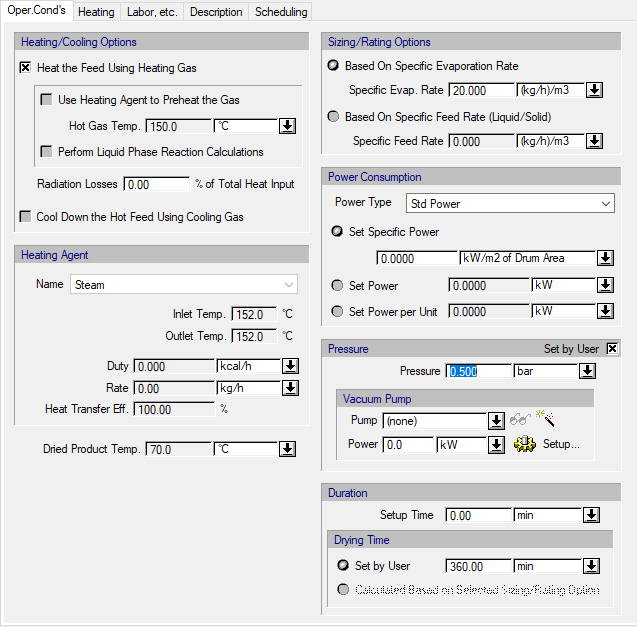
•Vacuum Pump Controls...
Note that the vacuum pump controls are only displayed if the operating pressure is less than the ambient pressure (specified through the flowsheet’s Reference Conditions dialog).
Click on the vacuum pump list box to bring up a list of available vacuum pumps in order to select one, or select “(none)” (default) if equipment sizing, costing and scheduling calculations are not important.
To create a new vacuum pump and add it to the list of available vacuum pumps, click on the New button (). This will open the Auxiliary Equipment Properties dialog for auxiliary equipment of the vacuum pump type (see Auxiliary Equipment Properties Dialog: Aux. Equipment tab (Vacuum Pump)). Through this dialog, you can view or edit the properties of the auxiliary equipment resource (e.g., name, size, purchase cost, consumables, scheduling).
The same dialog is displayed if you select one of the available vacuum pumps from the list and click on the View/Edit Properties button ().
Click on the Setup button to display the Vacuum Pump Consumption dialog (see Vacuum Pump Power Consumption Dialog), and select different options for specifying the power consumption of the vacuum pump. By default, the vacuum pump power specification option is “Set Total Power” and the total power consumption of the vacuum pump can be set by the user (the default value is zero). For more information, see Vacuum Pump Auxiliary Equipment Calculations.