eq. (A.189)
This model is used to simulate the behavior of a packed bed adsorption unit. Gas adsorption is used in industrial applications such as odor control; the recovery of volatile solvents such as benzene, ethanol, tricloroethylene, freon, and so forth; and the drying of process gas streams. The adsorbents used for air pollution control include activated carbon, alumina, bauxite and silica gel. Other special purpose adsorbents include acid-treated clay, aluminosilicate “sieves”, Fuller’s earth, iron oxide, and magnesia. Activated carbon is by far the most frequently used adsorbent and has virtually displaced all other materials in solvent recovery systems. Generally the capacity of an adsorbent to adsorb a particular adsorbate is directly proportional to the molecular weight and to the vapor pressure of the adsorbate. Typically the capacity of an adsorbent for a specific gas or vapor is represented by an isotherm which is extracted experimentally. There are, however several empirical or semi-empirical correlations that are used to capture adsorption isotherm data. The two most commonly used are Langmuir’s and Freundlich’s isotherm expressions.
● Granular Activated Carbon (GAC) Adsorption Procedure (for Gaseous Streams)
The user has to declare which components are likely to be withheld by the adsorption step and the binding percentages for each adsorbed component. These determine the fraction of the Feed stream that is adsorbed. This fraction will end up in the Regenerant Out stream during regeneration. The fraction of the Feed stream that is not adsorbed, exits from the bed through the Product Stream.
Based on the specified binding percentages, the program will calculate the overall binding efficiency of the unit.
According to Langmuir’s mathematical model, the adsorbing capacity q (in mg of adsorbate per g of adsorbent) relates to the adsorbate’s concentration C (in mg/L) as follows:
|
|
eq. (A.189) |
The above equation can actually be derived from first principles and is based on the assumptions that (a) the adsorbed phase is a unimolecular layer, and (b) at equilibrium, the rate of adsorption is equal to the rate of desorption from the surface.
Freundlich’s model on the other hand is purely empirical and states that the adsorbing capacity q (in mg of adsorbate per g of adsorbent) relates to the adsorbate’s concentration C (in mg/L) as follows:
|
|
eq. (A.190) |
Either model predicts the adsorption capacity at equilibrium. Under industrial conditions, the bed capacity will seldom exceed 30% or 40% of that indicated by an equilibrium isotherm. Factors to contribute to such a decrease include: the formation of an adsorption zone, loss due to heat wave, loss due to moisture in gas, loss due to residual moisture on adsorbent. Our model takes the adsorption capacity either directly as an input, or estimates the theoretical (equilibrium) capacity using either Langmuir’s or Freundlich’s equation and a correction factor (to account for practical losses) and the aggregate concentration at the input of all components that are expected to be adsorbed (set by user).
In Design mode, the total bed volume required by the operation is calculated as:
|
|
eq. (A.191) |
where:
● Fa is the adsorption rate of the Feed stream,
● tp is the breakthrough time,
● Wb is the adsorption capacity of the bed, and
● ρb is the bulk density of the bed.
During design mode, typically some design constraint restricts the size of each equipment selected. In this case, the design constraint can be either a maximum diameter, a maximum depth, or simply a maximum volume. The bed volume is calculated with respect to its diameter and depth as follows:
|
|
eq. (A.192) |
where:
● D is the bed diameter, and
● H is the bed depth.
When a maximum diameter, Dmax, is specified, the bed depth, H, is also specified and its diameter, D, is calculated from the above equation. When a maximum depth, Hmax, is specified, the bed diameter, D, is also specified and its height, H, is calculated from the above equation. When a maximum volume, Vb,max, is specified, the depth-to-diameter ratio, H/D, is also specified and the depth, H, and diameter, D, of the bed is calculated from the above equation. If D > Dmax, or H > Hmax, or Vb > Vb,max, then multiple units are assumed in parallel (i.e., in simultaneous operation).
If the procedure operates in continuous mode, additional units are required for regeneration. Even though some packed bed adsorption units today can be equipped with a mechanism for continuous regeneration (this option is not available by the simulation model) the majority of adsorption beds operate in two phases: adsorption followed by regeneration; therefore they are inherently cyclic. However, most plants operating under continuous conditions will stagger extra units so that the adsorption step is performed continuously. The model employed here will automatically estimate the extra units that are in waiting mode (Nw) for each unit in operation as:
|
|
eq. (A.193) |
where:
● ts is the setup time,
● tb is the breakthrough time, and
● tr is the regeneration time.
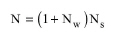
The total number of units that are required for continuous operation are then calculated as:
|
|
eq. (A.194) |
where Ns is the number of units in simultaneous operation.
The linear velocity of gas in the bed is calculated as:
|
|
eq. (A.195) |
where Q is the volumetric flow rate of gas in the bed and A is the cross-sectional area of the bed (A = πD2/4).
To estimate the actual fluid requirements for regeneration (typically steam) the user must either supply the mass of regeneration fluid required per bed volume or the mass of regeneration fluid required per mass of adsorbate. Based on these values and on the regeneration time, the required flow of regeneration fluid is determined.
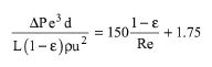
The pressure drop rate across the bed’s length can either be supplied by the user or it can be estimated based on Ergun’s equation:
|
|
eq. (A.196) |
1. C.David Cooper and F.C. Alley, (1990) Air Pollution Control: A Design Approach, McGraw-Hill, Inc.
2. D. W. Sundstrom, H. E. Klei, (1980) Wastewater Treatment, Prentice Hall, Inc.
The interface of this operation has the following tabs:
● Oper. Cond’s, see Packed-Bed Adsorption: Oper. Conds Tab
● Press. Drop, see Packed-Bed Adsorption: Pressure Drop Tab
● Ads. Capacity, see Packed-Bed Adsorption: Adsorption Capacity Tab
● Labor, etc, see Operations Dialog: Labor etc. Tab
● Description, see Operations Dialog: Description Tab
● Batch Sheet, see Operations Dialog: Batch Sheet Tab
● Scheduling, see Operations Dialog: Scheduling Tab