The purpose of this model is to simulate extraction in a multi-stage mixer-settler extractor. In the biochemical process industries, extraction is primarily used in the recovery and purification of antibiotics and other low to medium molecular weight products.
● Mixer-Settler Extraction Procedure
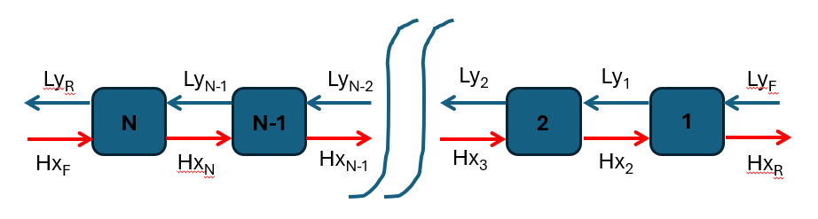
Material balances can be done based on component splits or partition coefficients. In the former case, the user specifies the fraction of each component that ends up in the top or bottom exit stream. The figure below shows a schematic representation of a counter-current extraction cascade with multiple stages.
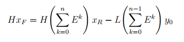
In the above representation, L and H are the volumetric flowrates and yi and xi are the component concentrations at stage i in the light and heavy phase, respectively (feed concentrations are denoted with F while exit (raffinate) concentrations are denoted with R. Two streams that exit from a stage are assumed to be at equilibrium described by a partition coefficient Ki = yi/xi. By considering the material balances around each stage with the assumption of constant volumetric flowrates for the heavy and light phases, one can derive the following equation:
|
|
where:
|
|
eq. (A.246) |
For E≠1 eq. (A.245) can be formed transformed into the closed form:
|
|
eq. (A.247) |
and for E=1 to:
|
|
eq. (A.248) |
Notice that partition coefficients refer exclusively to non-solvent components. To model solvent miscibility in two-solvent systems, the solubility of each solvent in the other phase should be specified. For single-solvent systems (e.g., aqueous two-phase systems used in biotechnology for the recovery and purification of proteins and other biological molecules), the user must specify the distribution, in terms of a fraction, of the single solvent between the two phases.
Recovery Definition and Number of Stages
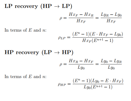
In Design Mode the user specifies a target product recovery yield ρ and the program calculates the number of theoretical stages required to achieve it. The recovery is defined as the fraction of product transferred into the receiving phase relative to the total product entering in that phase's feed stream:
|
|
eq. (A.249) |
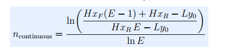
When the solvent flow is sufficient, the number of continuous theoretical stages, ncontinuous, for E≠1 is calculated from:
|
|
eq. (A.250) |
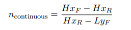
In the special case where E=1, the number of stages is equal to:
|
|
eq. (A.251) |
In rating mode the number of stages is given and the program will calculate the product recovery yield of the product component. Notice that in rating mode only, the product component specification is optional. This is useful when the goal is to simulate the solvent equilibrium (based on the solubilities in the heavy and light phase) rather than model the extraction of a specific product.
Minimum Solvent Flow for a Target Recovery Yield
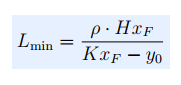
Before computing the number of stages, the program verifies that the solvent flow is sufficient to achieve the target recovery. The minimum solvent flow is derived from the pinch condition (the limiting case where the solvent exits in equilibrium with the incoming process stream) and is given by:
|
|
eq. (A.252) |
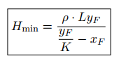
for recovery in the light phase and
|
|
eq. (A.253) |
for recovery in the heavy phase.
Recovery Direction
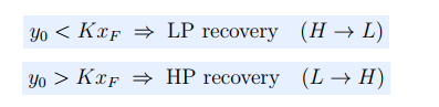
The direction of net transfer (i.e., whether the product is recovered in the heavy phase or the light phase) is determined automatically from the feed concentrations and the partition coefficient. If yF < K xF the driving force favors transfer from the heavy phase to the light phase (LP recovery). Conversely, if yF > K xF the driving force favors transfer from the light phase to the heavy phase (HP recovery). No net transfer is possible when yF = K xF, as the two feeds are at equilibrium. The above criteria are summarized in the equation below.
|
|
eq. (A.254) |
In Design Mode, the sizing of the mixer and settler tanks is based on the volumetric throughput the corresponding residence time that is specified by the user. If the operating throughput exceeds the maximum, the program assumes multiple units operating in parallel with a total throughput equal to the calculated. In rating mode, the size of the mixer and settler tank is provided by the user and the program calculates the corresponding residence times.
1. Belter, P. A., E. L. Cussler, and Wei-Shou Hu (1988). Bioseparations - Downstream Processing for Biotechnology, John Wiley & Sons.
The interface of this operation has the following tabs:
● Oper. Cond’s, see Mixer-Settler Extraction: Oper. Conds Tab
● Mat. Balance, see Mixer-Settler Extraction: Material Balance Tab
● Labor, etc, see Operations Dialog: Labor etc. Tab
● Description, see Operations Dialog: Description Tab
● Batch Sheet, see Operations Dialog: Batch Sheet Tab
● Scheduling, see Operations Dialog: Scheduling Tab