This operation models the pressure drop of liquids flowing through a control valve (globe or butterfly)
● Liquid Pressure Drop in a Globe Valve Procedure
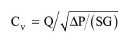
Given the flow rate through the valve and the pressure drop the required valve flow capacity (Cv) is calculated as:
|
|
where:
● Q is the liquid flow rate (in gallons per minute, GPM),
● ΔP is the pressure drop (in psi), and
● SG is the specific gravity of medium (relative to water).
One Cv unit corresponds to 1 GPM of water (at 60 F, SG =1) flowing with pressure drop of 1 psi. Note that most manufacturers provide valve data (Cv vs. Diameter) in the American units system. The program does all appropriate conversions to display all variables in SI, except for the flow capacity, which is displayed in the above units (‘Cv’).
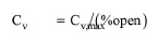
The fully open valve flow capacity (Cv,max) is then calculated from the % opening:
|
|
In Design Mode the user specifies the pressure drop and maximum diameter. A manufacturer chart, relating Cv,max and Diameter is used to calculate the diameter. If the calculated diameter exceeds the maximum specified, the program assumes multiple units operating in parallel with a total Flow Capacity (Cv,max) equal to the calculated.
In Rating Mode, the user specifies the diameter and number of units. The program uses the manufacturer’s chart to get the flow capacity and the resulting pressure drop.
|
|
As the Cv,max vs. Diameter data may vary from manufacturer to manufacturer, the user can use the calculated Flow Capacity (Cv,max) for obtaining the exact diameter from any manufacturer chart. |
The interface of this operation has the following tabs:
● Oper. Cond’s, see Globe Valve: Oper. Conds Tab
● Labor, etc, see Operations Dialog: Labor etc. Tab
● Description, see Operations Dialog: Description Tab
● Batch Sheet, see Operations Dialog: Batch Sheet Tab
● Scheduling, see Operations Dialog: Scheduling Tab