This unit operation simulates injection molding of polymeric resins for the formation of plastic objects. The primary objective of this model is to calculate the output capacity of the step based on the dimensions and thickness of the part, the physical properties of the resin, and the molding operating conditions. A secondary objective is to estimate the cost of the mold and the operating expenses associated with this step.
By default, the program calculates the part mass and volume based on the dimensions of the molded object. However, the user also has the option to specify either the mass or the volume of the molten resin that makes up the molded object. The conversion from mass to volume and vice-versa is done using the density of the resin. The specified part mass or volume must account for any extra material removed during trimming and/or reaming. Please note that in this version of SuperPro Designer, the density and the thermal diffusivity of the resin are properties local to the molding process steps. In future versions of the program, the values of these properties will be retrieved from the application component databank.
The shot weight (weight of material fed into the molding unit per cycle) is equal to the number of cavities times the part weight.
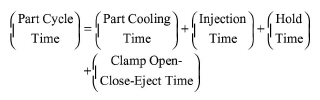
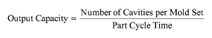
The output capacity of the unit is either specified by the user (based on vendor quotations) or calculated based on the part cycle time using the following equations:
|
|
|
|
eq. (A.352) |
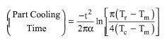
The values of Injection Time, Hold Time and Clamp Open-Close-Eject Time are machine-dependent and are always specified by the user. The Part Cooling Time is either specified by the user or calculated by the program using the following equation (Rosato and Rosato, p. 299):
|
|
eq. (A.353) |
where t is the maximum critical wall thickness, α is the thermal diffusivity of the resin, Tr is the heat distortion temperature, Tm is the mold temperature, and Tc is the melt temperature.
The Operating Output is calculated by dividing the feed flowrate by the amount of mass per part. The ratio of Operating Output over Output Capacity yields the Capacity Utilization. If the Capacity Utilization is over 100%, the user is advised by the program to either reduce the feed flowrate or increase the number of identical units that operate in parallel. Please note that a single molding icon can represent multiple molders (of the same capacity) operating in parallel. To represent that, you simply type an appropriate value for the Number of Units in the Equipment Tab.
The number of cavities Top to Bottom times Left to Right times the number of stacks per mold set (1 for single face, 2 for stack of two, or 4 for stack of four) yields the total number of cavities per mold set. The mold dimensions are calculated as a function of part height, number of cavities (top to bottom and left to right), horizontal movement, and type of mold (e.g., single face, stack of two, or stack of four).
The total cost per mold set is equal to the sum of the engineering design cost, the material and machining cost, and the hot runner cost. The material and machining cost, in turn, accounts for the cost of machining and the cost of the metal material. The machining cost is either specified by the user or calculated by the program based on the machining difficulty (which is specified by the user) and other mold attributes. The material cost is estimated based on the total mold weight and the unit cost of material ($/kg). Molds are usually made of stainless steel or aluminum alloys. The hot runner cost is estimated as a function of the number of cavities and the type of runner.
The cost of the mold can contribute to cost of consumables if the ‘Consider cost associated with mold replacement’ box is checked. Molds are usually replaced every 2-5 year of operation (specified by the replacement frequency variables). The annual consumable cost of a mold is estimated by dividing its total cost by its operating lifetime.
A mold also can contribute to capital investment if the ‘Capitalize Cost of First Mold Set’ box is checked. In that case, the mold cost is added to the equipment (molder) cost and it contributes to capital investment and other cost that depend on capital investment (e.g., maintenance, insurance, local taxes, etc.).
To account for electricity consumption, the user can specify the power requirement (in kW). Please note that this power requirement pertains to the molding operation only and it does not include the power requirement for the extruder. The extruder power demand is specified as part of the extrusion step.
1. Donald V. Rosato and Dominick V. Rosato, “Injection Molding Handbook”, 2nd Edition, Chapman Hall
The interface of this operation has the following tabs:
● Oper. Cond’s, see Injection Molding: Oper. Conds Tab
● Part, see Injection Molding: Part Tab
● Mold Data, see Injection Molding: Mold Data Tab
● Cost Data, see Injection Molding: Cost Data Tab
● Labor, etc, see Operations Dialog: Labor etc. Tab
● Description, see Operations Dialog: Description Tab
● Batch Sheet, see Operations Dialog: Batch Sheet Tab
● Scheduling, see Operations Dialog: Scheduling Tab