eq. (A.335)
This operation models the transfer of heat from a hot to a cold stream through the use of a heat exchanger. The heat exchanger can be of Plate & Frame, Spiral, or Shell and Tube type. Several options are available for specifying performance specifications and operating conditions.
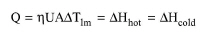
The energy balance is represented by the following equation:
|
|
eq. (A.335) |
where:
● Q is the heat transfer (exchange) rate or load (kcal/h),
● η is a correction factor that accounts for deviations from counter-current or co-current flow
● U is the overall heat transfer coefficient (kcal/h-°C-m2),
● A is the heat transfer area (m2),
● ΔTlm is the log mean temperature difference in the system (the driving force) (°C),
● m is the mass flowrate of the stream (kg/h),
● cp is the specific heat capacity of the stream (kcal/kg-°C), and
● ΔHhot and ΔHcold are the enthalpy changes of the hot and cold streams, respectively, between inlet and outlet conditions (kcal/h).
The above equation holds only if the temperature profiles of the hot and cold streams along the heat exchanger do not cross each other (in other words, the temperature difference between the hot and cold streams at either end of the heat exchanger should be positive). The enthalpy change of each stream will take into account changes in both sensible and latent heat (in case of condensation/vaporization of hot/cold stream).
The value of U is always specified by the user. The values of m and cp are always calculated based on the stream flows and compositions. The values of ΔTi (temperature differences between entrance/exit conditions for cold and hot stream) are calculated based on the performance specifications. The performance specifications can be one of the following:
● Exit temperature of the cold stream
● Exit temperature of the hot stream
● Temperature increase of the cold stream
● Temperature drop of the hot stream
● Allowable temperature difference at either end of the heat exchanger (Min Allowable Temp Diff)
The value of Q (heat exchanger load) is always calculated and presented in the operation’s i/o dialog.
In Design Mode, the above equations are solved for A (area) such that any of the available performance criteria is satisfied. If the calculated area exceeds the maximum heat transfer area, the program assumes multiple units operating in parallel with a total heat transfer area equal to the calculated.
In Rating Mode, in order to avoid predicting exit temperatures that may violate the assumption on which the above equipment performance equation is based, we first calculate the area that may lead to a minimum achievable temperature approach (it can’t be set to 0 but it can be set to a small number). This would be the area beyond which no more heat exchange is feasible. Then, we check the calculated value against the available area. If the available area is smaller, we solve the above two equations (heat balance and equipment performance) to find out the exit temperatures of the streams. If the available area is larger than what’s required to achieve the minimum achievable temperature difference, we compute the exit conditions using the minimum achievable temperature difference. Essentially in this case the heat exchanger is over-designed (not all of the exchange are is functional).
The interface of this operation has the following tabs:
● Oper. Cond’s, see Heat Exchanging: Oper. Conds Tab
● Labor, etc, see Operations Dialog: Labor etc. Tab
● Description, see Operations Dialog: Description Tab
● Batch Sheet, see Operations Dialog: Batch Sheet Tab
● Scheduling, see Operations Dialog: Scheduling Tab