eq. (A.406)
This operation is used to simulate the conversion of liquid/solid fuel (coal, biomass, etc.) into gaseous fuel in a gasifier. The liquid/solid fuel reacts with oxidant (air or oxygen) and moderator (steam) to produce producer gas (a mixture consisting mainly of CO, H2, CH4, CO2 and H2O) and liquid/solid waste (ash, unburned carbon, etc.). The gasifier can be either adiabatic or externally heated. In the adiabatic case, since there is no external heat source, the gasification must be self-sustained, and the overall gasification reaction must be exothermic. In that case, the heat required to carry out endothermic gasification reactions is provided by burning part of the fuel. To simulate an externally heated gasifier, a heat transfer agent must be used to represent the external heat source, and either the heat source or the final temperature must be specified. The composition of the producer gas at chemical equilibrium can be estimated by either assuming that certain stoichiometric reactions take place or by applying the Gibbs Energy Minimization method. Optionally, a shift from chemical equilibrium may be assumed for each stoichiometric reaction.
Fuel, oxidant and, optionally, moderator are fed into the hosting equipment continuously through the designated input ports for fuel, oxidant, and moderator streams, respectively. The fuel stream carries the fuel that is going to be gasified. It may contain one or more dry fuel components and (optionally) water. The oxidant stream carries the oxygen required for gasification (typically, in the form of air or “Oxygen” component). The moderator stream carries steam which is used to control the gasification temperature. These streams may also contain inert components. These are gaseous or liquid/solid components that do not participate in gasification reactions (e.g., nitrogen). Any inert gaseous components in the inlet mixture, as well as any gases produced by gasification, are transferred to the designated output port that is connected to the producer gas stream. Any inert liquid/solid components of the inlet mixture are transferred together with fuel ash and unconverted carbon to the designated output port that is connected to the ash stream.
This model simulates the gasification of fuel in the presence of oxidant (air or oxygen) and optionally moderator (steam) to produce a gaseous fuel consisting mainly of CO, H2, CH4, CO2 and H2O.
The user can specify the following parameters through the interface of this operation:
Oper. Conds Tab (see Gasification: Oper. Conds Tab):
● The chemical equilibrium calculation option. This can be either based on the equilibrium constants of a known set of gasification reactions (“Equilibrium Constants” option) or on the Gibbs energy minimization method (“Gibbs Energy Minimization” option).
● The option to specify a shift from chemical equilibrium for each gasification reaction (“Set?” option). Note that this option is available only if the “Equilibrium Constants” option is selected.
● If the “Set?” option is checked for the shift from chemical equilibrium, then it is possible to specify user-defined values for the percent shift from chemical equilibrium of the water-gas shift and methane reactions.
● The oxidant stream flow specification option. The flow of the oxidant stream can be either specified directly through the stream’s simulation data dialog (“Available in Stream” option) or it can be calculated based on the specified equivalence ratio (“Calculated Based on Equivalence Ratio” option.
● The equivalence ratio (only if the “Calculated Based on Equivalence Ratio” option is selected).
● The option to include the moderator stream in the calculations (“Include?” option).
● The moderator stream flow specification option. The flow of moderator can be either specified directly through the stream’s simulation data dialog (“Available in Stream” option) or it can be calculated based on the specified steam/carbon ratio (“Calculated Based on Steam/Carbon Ratio” option).
● The steam/carbon mol ratio (only if the “Calculated Based on Steam/Carbon Ratio” option is selected).
● The thermal mode option (“Set Final Temperature”, “Adiabatic”, or “Set Heating Duty”).
● The final temperature (only if the thermal mode option is set to “Set Final Temperature”).
● The heating duty (only if the thermal mode option is set to “Set Heating Duty”).
● The selected heating agent and heat transfer efficiency (only if the thermal mode option is set to “Set Final Temperature” or “Set Heating Duty”; if the thermal mode is set to “Adiabatic”, no heating agent is used).
● The operating pressure.
● The carbon conversion %.
● The overall heat losses to the walls and surroundings (expressed as percentage of the total HHV of all dry fuel components).
Fuel tab (see Fuel Conversion: Fuel Tab):
● The option to check one or more pure components contained in the fuel stream as dry fuel (i.e., dry combustible matter) (“Fuel?” option).
● For each component that is set as dry fuel, the elemental C, H, O, N and S composition on dry basis, the ash content on dry basis, and the HHV on dry basis.
Species tab (see Gasification: Species Tab):
● The pure components that are associated with species that may be present in the output streams (oxygen, water, nitrogen, hydrogen, carbon monoxide, carbon dioxide, methane, hydrogen sulfide, ash and carbon).
Numerics tab (see Gasification: Numerics Tab):
● Initial guess values for the mol % of carbon dioxide, carbon monoxide, hydrogen and methane in the product gas.
● An initial guess for the final temperature (only in the adiabatic case).
● Initial guess values for the Lagrange multipliers of the carbon, hydrogen and oxygen elements (only in the case that the chemical equilibrium is calculated based on the Gibbs Energy Minimization method).
Based on the above parameters, the model will calculate the following:
Oper. Conds Tab (see Gasification: Oper. Conds Tab):
● Either the oxidant stream flow or the equivalence ratio (whichever is not set by the user).
● If a moderator stream is included, either the moderator stream flow or the steam/carbon ratio (whichever is not set by the user).
● The final temperature (if not set by the user).
● The heating duty (if not set by the user) and heating agent rate.
● The flow and composition of the producer gas and ash streams.
● The volumetric dry gas production rate at STP, where STP refers to the standard temperature and pressure specified for the flowsheet; by default, the standard temperature and pressure for a new flowsheet are 0oC and 1 bar; these values can be changed through the dialog that is displayed when the you right-click on empty space in the flowsheet and then you click “Reference Conditions...” on the menu that pops-up.
● The cold gas efficiency on higher heating value (HHV) basis.
● The cold gas efficiency on lower heating value (LHV) basis.
● The hot gas efficiency on higher heating value (HHV) basis.
● The hot gas efficiency on lower heating value (LHV) basis.
Numerics tab (see Gasification: Numerics Tab):
● The initial guess for the mol % of water vapor in the product gas.
● The final solution for the mol % of carbon dioxide, carbon monoxide, hydrogen, methane and water vapor in the product gas.
● The final solution for the Lagrange multiplier of the carbon, hydrogen and oxygen element (only if the chemical equilibrium is based on the Gibbs Energy Minimization method).
● The final solution for the final temperature.
Energy Balance tab (Gasification: Energy Balance Tab):
● The percentage of dry fuel in the fuel stream.
● The percentage of water in the fuel stream.
● The higher heating value of dry fuel.
● The lower heating value of dry fuel.
● The enthalpy of the fuel stream at standard state and 25oC.
● The enthalpy of the fuel stream.
● The heat required to vaporize any liquid water that may exist in the fuel stream calculated based on the latent heat of vaporization of water at 1 bar and 25oC.
● The percentage of water in the oxidant stream.
● The enthalpy of the oxidant stream at standard state and 25oC.
● The enthalpy of the oxidant stream.
● The heat required to vaporize any liquid water that may exist in the oxidant stream calculated based on the latent heat of vaporization of water at 1 bar and 25oC.
● The percentage of water in the moderator stream.
● The enthalpy of the moderator stream at standard state and 25oC.
● The enthalpy of the moderator stream.
● The heat required to vaporize any liquid water that may exist in the moderator stream calculated based on the latent heat of vaporization of water at 1 bar and 25oC.
● The percentage of dry producer gas in the producer gas stream.
● The percentage of water in the producer gas stream.
● The enthalpy of the producer gas stream at standard state and 25oC.
● The enthalpy of the producer gas stream.
● The heat required to condense any water vapor that may exist in the producer gas stream calculated based on the latent heat of vaporization of water at 1 bar and 25oC.
● The higher heating value of the ash stream. This is the same as the lower heating value of that stream..
● The enthalpy of the ash stream at standard state and 25oC.
● The enthalpy of the ash stream.
● The sum of the enthalpy changes with respect to standard enthalpy for all inlet streams considered (fuel, oxidant, and optionally, moderator).
● The sum of the enthalpy changes with respect to standard enthalpy for all outlet streams (producer gas and ash).
● The standard enthalpy of the overall gasification reaction at 25 oC.
● The heat losses to walls and surroundings.
If the equipment is in Design mode, the operation will also size the equipment and calculate the operating throughput per unit.
Model calculations are described below in more detail.
The fuel stream may contain one or more dry fuel components and (optionally) moisture.
The following data must be specified for each dry fuel component present in the feed stream through the Fuel tab (see Fuel Conversion: Fuel Tab):
● Elemental C, H, O, N, and S composition on dry basis (i.e., element mass per total mass of dry fuel component).
● Ash content on dry basis (i.e., ash mass per total mass of dry fuel component).
● Higher heating value (HHV) of dry fuel component on dry basis (i.e., energy per kg of dry fuel component).
The higher heating value (HHV) of a fuel is defined as the amount of heat released per unit mass of that fuel (initially at 25 oC) once it is fully combusted and the combustion products have returned to the original pre-combustion temperature. Therefore, it includes the heat released during combustion and the heat recovered by condensing any water vapor produced by combustion.
Moisture is represented by the pure component that is associated with the “Water” species in the Species tab (see Gasification: Species Tab). In the same tab, the following additional species can be associated with registered pure components: “Oxygen”, “Nitrogen”, “Hydrogen”, “Carbon Monoxide”, “Carbon Dioxide”, “Methane”, “Hydrogen Sulfide”, “Ash” and “Carbon”. If any of the above species exists in the system (either as reactant or product) then it must be associated with a registered pure component. For example, if a dry fuel contains ash, then an equal amount of ash must be contained in the ash stream by means of a pure component. Therefore, a suitable pure component (e.g., the “Ash” pure component of the Designer database) must be registered first (see Pure Component Registration for more details) Then, the registered pure component can be associated with the “Ash” species through this tab. In a similar manner, if unconverted carbon exists in the ash stream, then a suitable pure component (e.g. “Carbon”) must be registered and associated with the “Carbon” species. By default, the “Oxygen”, “Nitrogen” and “Water” species are associated with the respective “Oxygen”, “Nitrogen” and “Water” pure components of the Designer database. You may also associate the “Hydrogen”, “Carbon Monoxide”, “Carbon Dioxide”, “Methane” and “Hydrogen Sulfide” species with the respective “Hydrogen”, “Carbon Monoxide”, “Carbon Dioxide”, “Methane” and “Hydrogen Sulfide” pure components of the Designer database. Note that a pure component is required for the “Hydrogen Sulfide” species only if one or more dry fuel components contain sulfur.
The fuel stream may also contain pure components that do not have any of the above species. These are considered inert components. Any gaseous inert component present in the fuel stream (as well as in any input stream) will be transferred to the gas stream. Any liquid/solid inert component present in the fuel stream (as well as in any input stream) will be transferred to the ash stream.
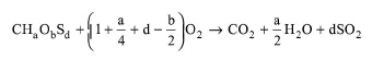
The empirical formula n(CHaObNcSd + wfH2O) is assumed for each dry fuel component, where:
● n is the atoms of C per kg of dry fuel component,
● a is the atoms of H per atom of C,
● b is the atoms of O per atom of C,
● c is the atoms of N per atom of C, and
● d is the atoms of S per atom of C.
The following combustion reaction is considered for each dry fuel component:
|
|
eq. (A.406) |
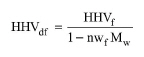
The higher heating value of a dry fuel component may be calculated based on the higher heating value of the respective wet fuel component as follows:
|
|
eq. (A.407) |
where:
● HHVdf is the higher heating value of the dry fuel component (in kJ/kg dry)
● HHVf is the higher heating value of the wet fuel component (in kJ/kg wet)
● Mw is the molecular weight of water (in kg/mol)
● wf is the moles of fuel moisture per atom of C.
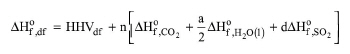
For each dry fuel component, the higher heating value may also be estimated as the negative standard heat of combustion of that component. Based on the definition of standard heat of combustion, the following equation may be derived for calculating the standard enthalpy of formation of each dry fuel component:
|
|
eq. (A.408) |
where:
● ΔΗοf,df is the standard enthalpy of formation of the dry fuel component (in kJ/kg dry)
● HHVdf is the higher heating value of the dry fuel component (in kJ/kg dry)
● ΔΗοf,CO2 is the standard enthalpy of formation of CO2 (in kJ/mol)
● ΔΗοf,H2O(l) is the standard enthalpy of formation of liquid water (in kJ/mol)
● ΔΗοf,SO2 is the standard enthalpy of formation of SO2 (in kJ/mol)
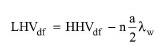
The lower heating value (LHV) of a fuel corresponds to the heat released per unit mass if that fuel is fully combusted and no heat is recovered by condensing any produced vapors. For each dry fuel component, the lower heating value can be estimated by subtracting the heat of condensation of water vapor produced by combustion (calculated at 1 bar and 25 oC) from the respective higher heating value:
|
|
where:
● LHVdf is the lower heating value of the dry fuel component (in kJ/kg dry)
● λw is the latent heat of vaporization of water at 1 bar and 25oC (~44 kJ/mol) (in kJ/mol)
The standard state (used in M&E balance calculations) is defined as follows:
● The pressure is 1 bar (standard pressure).
● The physical state of the water component is vapor.
● The physical state of all other components is determined based on the Antoine vapor/liquid split criterion for standard pressure and 25oC. For more information on this criterion, see Physical State Calculation Options).
The following reactions are considered:
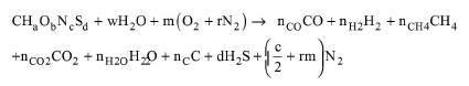
Global gasification reaction:
|
|
eq. (A.410) |
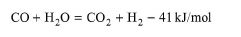
Water-gas shift reaction (exothermic):
|
|
eq. (A.411) |
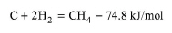
Methane reaction (exothermic):
|
|
eq. (A.412) |
where:
● w is the initial moles of H2O (fuel moisture + water vapor in air + steam) per atom C
● m is the initial moles of O2 per atom C
● r is the N2/O2 ratio of air in the oxidant stream (if any)
● nCO2 is the moles of produced CO2 per atom C
● nCO is the moles of produced CO per atom C
● nH2 is the moles of produced H2 per atom C
● nCH4 is the moles of produced CH4 per atom C
● nH2O is the moles of produced H2O per atom C
● nC is the moles of unconverted C per atom C
Note that the carbon conversion, xC, is equal to 1-nC.
Also note that the water-gas shift reaction can be derived by combining the steam gasification reaction and the Boudouard reaction. These reactions are described below:
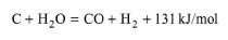
Steam gasification reaction (endothermic):
|
|
eq. (A.413) |
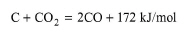
Boudouard reaction (endothermic):
|
|
eq. (A.414) |
In this simulation model, the global gasification reaction, the water-gas shift reaction and the methane reaction are considered. Based on these reactions, the following six equations are derived:
Carbon balance equation:
|
|
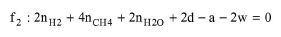
Hydrogen balance equation:
|
|
Oxygen balance equation:
|
|
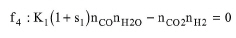
Chemical equilibrium equation of water-gas shift reaction:
|
|
eq. (A.418) |
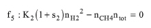
Chemical equilibrium equation of methane reaction:
|
|
eq. (A.419) |
where:
● K1 is the equilibrium constant of the water-gas shift reaction
● K2 is the equilibrium constant of the methane reaction
● s1 is the shift from equilibrium for the steam gasification reaction
● s2 is the shift from equilibrium for the methane reaction
The equilibrium reaction constant at the reaction temperature T is calculated as:
|
|
eq. (A.420) |
where:
● ΔG is the change in the Gibbs free energy of the reaction (in kJ/mol)
● R is the universal gas constant (in kJ/mol-K)
● T is the reaction temperature (in K)
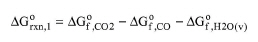
The change in the Gibbs free energy of the two equilibrium reactions considered is given by:
|
|
eq. (A.421) |
|
|
eq. (A.422) |
where:
● ΔGorxn,1 is the change in the Gibbs free energy of the water-gas shift reaction (in kJ/mol)
● ΔGorxn,2 is the change in the Gibbs free energy of the methane reaction (in kJ/mol)
● ΔGof,CO2 is the standard Gibbs free energy of formation of CO2 (in kJ/mol)
● ΔGof,CO is the standard Gibbs free energy of formation of CO (in kJ/mol)
● ΔGof,H2O(v) is the standard Gibbs free energy of formation of H2O(v) (in kJ/mol)
● ΔGof,CH4 is the standard Gibbs free energy of formation of CH4 (in kJ/mol)
The standard Gibbs free energy of formation is calculated with respect to temperature using an empirical built-in model (Jarungthammachote and Dutta, 2007).
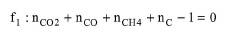
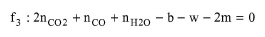
The system of MB equations consists of the following three atom balances for C, H and O, respectively:
|
|
|
|
|
|
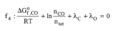
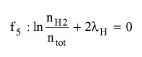
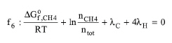
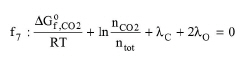
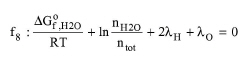
It also includes the minimization equations for species CO, H2, CH4, CO2, H2O and unconverted C:
|
|
eq. (A.423) |
|
|
eq. (A.424) |
|
|
eq. (A.425) |
|
|
eq. (A.426) |
|
|
eq. (A.427) |
|
|
eq. (A.428) |
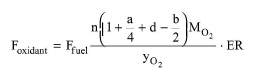
The relation between oxidant stream flow and equivalence ratio is given by the following equation:
|
|
eq. (A.429) |
where:
● Foxidant is the mass flow rate of the oxidant stream (in kg/s)
● Ffuel is the mass flow rate of the fuel stream (in kg/s)
● MO2 is the molecular weight of oxygen (in kg/mol)
● yO2 is the mass fraction of oxygen in the oxidant stream (in kg/kg)
● ER is the equivalence ratio (i.e., the ratio of actual oxygen amount in oxidant stream to the stoichiometric oxygen amount required for complete combustion of fuel in the fuel stream).
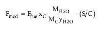
The relation between moderator stream flow and steam/carbon mol ratio is given by the following equation:
|
|
eq. (A.430) |
where:
● Fmod is the mass flow rate of the moderator stream (in kg/s)
● xC is the mass fraction of elemental carbon in the fuel stream (in kg/kg)
● MH2O is the molecular weight of water (in kg/mol)
● MC is the molecular weight of carbon (in kg/mol)
● yH2O is the mass fraction of water in the moderator stream (in kg/kg)
● S/C is the steam/carbon mol ratio (i.e., the ratio of the moles of water in the moderator stream to the moles of carbon in the fuel stream).
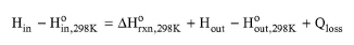
The overall enthalpy balance is as follows:
|
|
eq. (A.431) |
where:
● Hin is the total inlet enthalpy (in kJ/kg of fuel stream)
● Hout is the total outlet enthalpy (in kJ/kg of fuel stream)
● Hoin,298K is the total inlet enthalpy at standard state and at 25 oC (in kJ/kg of fuel stream)
● Hoout,298K is the total outlet enthalpy at standard state and at 25 oC (in kJ/kg of fuel stream)
● ΔHorxn,298K is the standard enthalpy of the overall gasification reaction at 25 oC (in kJ/kg of fuel stream)
● Qloss is the heat losses to the surroundings (in kJ/kg of fuel stream)
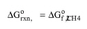
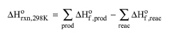
The standard heat of the overall gasification reaction at 25 oC is calculated as:
|
|
eq. (A.432) |
where:
● ΔHof,prod is the standard enthalpy of formation of each product of the overall gasification reaction (in kJ/kg of fuel stream)
● ΔHof,reac is the sum of the standard enthalpies of formation of each reactant of the overall gasification reaction (in kJ/kg of fuel stream)
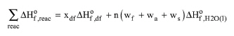
The sum of the standard enthalpies of formation of all reactants is:
|
|
eq. (A.433) |
where:
● xdf is the mass fraction of dry fuel in the fuel stream.
● wf is the moles of water in the fuel stream per atom C of all dry fuel components.
● wa is the moles of water in the oxidant stream per atom C of all dry fuel components.
● ws is the moles of water in the moderator stream per atom C of all dry fuel components.
Note that w = wf + wa + ws.
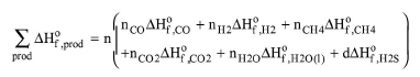
The sum of the standard enthalpies of formation of all products is:
|
|
eq. (A.434) |
where:
● ΔΗοf,CO is the standard enthalpy of formation of CO (in kJ/mol)
● ΔΗοf,H2 is the standard enthalpy of formation of H2 (in kJ/mol)
● ΔΗοf,CH4 is the standard enthalpy of formation of CH4 (in kJ/mol)
● ΔΗοf,H2S is the standard enthalpy of formation of H2S (in kJ/mol)
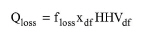
The heat losses to walls and surroundings are calculated as:
|
|
eq. (A.435) |
where:
● floss is fraction of the HHV of dry fuel that is lost to walls and surroundings.
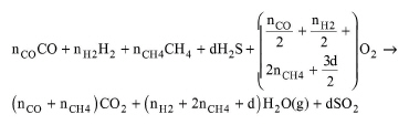
The following reaction is considered for the complete combustion of dry producer gas:
|
|
eq. (A.436) |
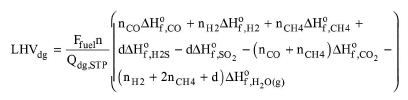
The LHV of the dry producer gas can be calculated as:
|
|
eq. (A.437) |
where:
● LHVdg is the lower heating value of dry producer gas (in kJ/Nm3).
● Qdg,STP is volumetric dry gas production rate at standard temperature and pressure (STP) (in Nm3/s).
● CGEHHV is the cold gas efficiency on HHV basis.
● Fdg is the mass flow rate of dry producer gas (in kg/s).
● Fdf is the mass flow rate of dry fuel (in kg/s).
The standard temperature and pressure is specified for the entire flowsheet. By default, the standard temperature is 0oC and the standard pressure is 1 bar. To access these properties, right-click on empty space in the flowsheet and click “Reference Conditions...” on the menu that pops-up.
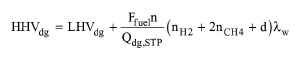
The HHV of the dry producer gas can be calculated as:
|
|
eq. (A.438) |
where:
● HHVdg is the higher heating value of dry producer gas (in kJ/Nm3).
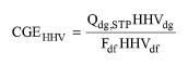
The cold gas efficiency is useful when the product gas is cooled prior to further use. The cold gas efficiency on HHV basis can be calculated as:
|
|
eq. (A.439) |
where:
● CGEHHV is the cold gas efficiency on HHV basis.
● Fdf is the mass flow rate of dry fuel (in kg/s).
The cold gas efficiency on LHV basis can be calculated by a similar equation to the above if the HHVdgand HHVdf are replaced by LHVdg and LHVdg, respectively.
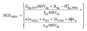
The hot gas efficiency is useful when the product gas is used as it is (hot) in a furnace or burner. The hot gas efficiency on HHV basis can be calculated as follows:
|
|
eq. (A.440) |
where:
● HGEHHV is the hot gas efficiency on HHV basis.
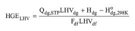
● Hdg is the enthalpy of the dry producer gas stream (in kW).
● Hodg,298K is the enthalpy of the dry producer gas stream at standard state and 25 oC (in kW).
The hot gas efficiency on LHV basis can be calculated as:
|
|
eq. (A.441) |
where:
● HGELHV is the hot gas efficiency on LHV basis.
The following components are transferred to the producer gas stream:
a) Any inert gaseous components contained in the input streams (e.g., nitrogen).
b) Product gas components (CO, CO2, H2, CH4, H2O, and H2S).
The following components are transferred to the ash stream:
a) Any inert liquid/solid components contained in the input streams (e.g., ash).
b) Any ash in the fuel and any unconverted carbon.
In Design mode, the user specifies the maximum fuel throughput of the gasifier. If the operating fuel throughput exceeds the specified maximum, the program assumes multiple units operating in parallel with a total fuel throughput equal to the calculated one.
If the equipment size option is in Rating Mode, the user specifies the rated fuel throughput and the number of units. If the calculated fuel throughput per unit exceeds the rated value, a warning message is displayed advising the user to increase the rated value or the number of units.
1. Basu P. Biomass Gasification and Pyrolysis Practical Design and Theory. Elsevier, 2010.
2. Jarungthammachote S. and A. Dutta. Thermodynamic equilibrium model and second law analysis of a downdraft waste gasifier. Energy, 32, pp. 1660-1669, 2007.
3. Jarungthammachote S. and A. Dutta. Equilibrium modeling of gasification: Gibbs free energy minimization approach and its application to spouted bed and spout-fluid bed gasifiers. Energy Conversion and Management, 49, pp. 1345-1356, 2008.
● Only the fuel stream can contain fuel components.
● The oxidant stream must contain a pure component associated with the “Oxygen” species.
● The moderator stream must contain a pure component associated with the “Water” species.
● The heat of fusion of ash is neglected.
● Preheating of the inlet streams by the product gas is neglected.
The interface of this operation has the following tabs:
● Oper. Cond’s, see Gasification: Oper. Conds Tab
● Fuel, see Fuel Conversion: Fuel Tab
● Species, see Gasification: Species Tab
● Numerics, see Gasification: Numerics Tab
● Energy Balance, Gasification: Energy Balance Tab
● Labor, etc, see Operations Dialog: Labor etc. Tab
● Description, see Operations Dialog: Description Tab
● Batch Sheet, see Operations Dialog: Batch Sheet Tab
● Scheduling, see Operations Dialog: Scheduling Tab