This operation models the pressure drop of gases flowing through a control valve (globe or butterfly). The model described below is valid for small pressure drops in gas flow. The flow capacity formula, for calculating the Cv of a valve was design for liquid flow and is expressed in “GPM of water (at 60 F – S.G. =1) flowing with pressure drop of 1 psi”. However this flow capacity (in the same units) and similar formula is used for gas flow through a valve.
● Gas Pressure Drop in a Globe Valve Procedure
Two different pressure regimes are considered for the sizing a valve for gas flow depending on the relative values of the inlet and outlet pressures (P1 and P2). In both cases the required valve flow capacity (Cv) is calculated given the flow rate through the valve and the pressure drop.
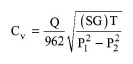
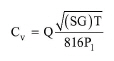
Critical (or Chocked) Flow regime: Valid when (P1 ³ 2P2).
|
|
where:
● Q is the gas flow rate (in standard cubic feet per hour),
● SG is the specific gravity of medium, relative to air at 70 F and 14.7 psia (where SG is 1.0),
● P1 is the inlet pressure (in psi),
● T is the absolute temperature (in degrees R).
One Cv unit corresponds to 1 GPM of water (at 60 F, SG =1) flowing with pressure drop of 1 psi.
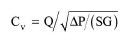
Subcritical Flow Regime: Valid when (P1< 2P2).
|
|
where P2 is the outlet pressure (in psi). Note that most manufacturers provide valve data (Cv vs. Diameter) in the American units system. The program does all appropriate conversions to display all variables in SI, except for the flow capacity, which is displayed in the above units (‘Cv’).
The fully open valve flow capacity (Cv,max) is then calculated from the % opening:
|
|
In Design Mode the user specifies the pressure drop and maximum diameter. A manufacturer chart, relating Cv,max and Diameter is used to calculate the diameter. If the calculated diameter exceeds the maximum specified, the program assumes multiple units operating in parallel with a total Flow Capacity (Cv,max) equal to the calculated.
In Rating Mode, the user specifies the diameter and number of units. The program uses the manufacturer’s chart to get the flow capacity and the resulting pressure drop.
|
|
As the Cv,max vs. Diameter data may vary from manufacturer to manufacturer, the user can use the calculated Flow Capacity (Cv,max) for obtaining the exact diameter from any manufacturer chart. |
The interface of this operation has the following tabs:
● Oper. Cond’s, see Globe Valve: Oper. Conds Tab
● Labor, etc, see Operations Dialog: Labor etc. Tab
● Description, see Operations Dialog: Description Tab
● Batch Sheet, see Operations Dialog: Batch Sheet Tab
● Scheduling, see Operations Dialog: Scheduling Tab