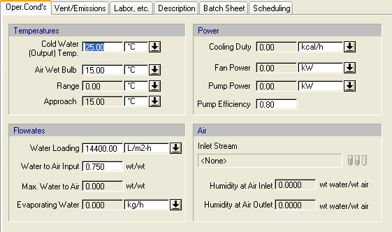
The following table shows a brief description of the variables appearing in this tab. The table also displays their default values and their generally acceptable range:
|
Variable |
Default Value |
Range |
|
|
||
|
○ Water Component Name |
<Water> |
Any Pure Component |
|
● Hot Water Temperature (°C) |
25.0 |
Positive |
|
○ Cold Water Temperature (°C) |
25.0 |
Positive |
|
○ Drift (% of Hot Water) |
0.0 |
[0,100) |
|
○ Blowdown (% of Cold Water) |
0.0 |
[0,100) |
|
● Inlet Air Stream Name |
<None> |
Dedicated Input Port |
|
○ Water to Air Ratio (wt/wt) |
0.75 |
Positive |
|
● Max Water to Air Ratio (wt/wt) |
0.0 |
Positive |
|
● Inlet Air Dry-Bulb Temperature (°C) |
25.0 |
Positive |
|
◙ Inlet Air Wet-Bulb Temperature (°C) |
15.0 |
Positive |
|
◙ Inlet Air Relative Humidity (%) |
50.0 |
Positive |
|
● Inlet Air Humidity (wt water/wt dry air) |
0.0 |
Positive |
|
● Inlet Air Water Vapor (%) |
0.0 |
[0,100) |
|
● Outlet Air Humidity (wt water/wt air) |
0.0 |
Positive |
|
● Makeup Stream Name |
<None> |
Dedicated Input Port |
|
● Cooling Range (°C) |
0.0 |
Positive |
|
● Approach Temperature (°C) |
15.0 |
Positive |
|
● Cooling Load (kcal/h) |
0.0 |
Positive |
|
● Evaporating Water (kg/h) |
0.0 |
Positive |
|
○ Water Loading (m3/m2-h) |
14.4 |
3-22.5 |
|
○ Power Type |
<Std Power> |
Any Power Type |
|
○ Include Induced Draft Fan? |
Yes |
Yes/No |
|
○ Induced Draft Fan Pressure Change (bar) |
0.005 |
Positive |
|
○ Induced Draft Fan Efficiency (%) |
80.0 |
(0,100) |
|
● Induced Draft Fan Power (kW) |
0.0 |
Positive |
|
○ Include Cold Water Pump? |
Yes |
Yes/No |
|
○ Cold Water Pump Pressure Change (bar) |
3.000 |
Positive |
|
○ Cold Water Pump Efficiency (%) |
70.0 |
(0,100) |
|
● Cold Water Pump Power (kW) |
0.0 |
Positive |
Symbol Key: ○ User-specified value (always input); ● Calculated value (always output); ◙ Sometimes input, sometimes output
The following list describes the available specification choices in this tab; for more details on how these are implemented, see Cooling in a Cooling Tower: Modeling Calculations.
•Drift ...
You don’t need to add a drift stream if the drift % is zero.
•Blowdown...
You don’t need to add a blowdown stream if the drift % is zero.
•Inlet Air Stream Humidity Specification Options...
If you select the “Available in Stream” option, the mass fraction of water in the inlet air stream is used to calculate the inlet air stream’s humidity, wet-bulb temperature, and relative humidity.
If you select the “Calculated Based On Wet-Bulb-Temperature” option, you must specify the inlet air stream’s wet-bulb temperature. The program will then calculate the inlet air stream’s humidity and relative humidity based on this value. In this case, the moisture content of the inlet air stream can be left as zero. However, if the moisture content of the inlet air stream is not zero and its corresponding humidity differs significantly from the model’s calculated inlet air humidity, a warning message will be displayed.
If you select the “Calculated Based On Relative Humidity” option, you must specify the inlet air stream’s relative humidity. The program will then calculate the inlet air stream’s humidity and wet-bulb temperature based on this value. In this case, the moisture content of the inlet air stream can be left as zero. However, if the moisture content of the inlet air stream is not zero and its corresponding humidity differs significantly from the model’s calculated inlet air humidity, a warning message will be displayed.
•Makeup Stream...
Add a makeup stream containing a water component to let the program calculate the mass flow rate of makeup water (added water that accounts for evaporated, drift, and blowdown water so that the inlet and outlet water mass flowrates are the same). If you don’t add a makeup stream, zero makeup water will be assumed.
•Induced Draft Fan...
You may check the “Include?” option to let the program calculate the power consumption of the cooling tower’s induced draft fan. Alternatively, you may choose to uncheck this option and add an explicit fan procedure to the flowsheet to simulate the cooling tower’s fan.
•Cold Water Pump...
You may check the “Include?” option to let the program calculate the power consumption of the cooling tower’s cold water pump. Alternatively, you may choose to uncheck this option and add an explicit pump procedure to the flowsheet to simulate the cooling tower’s water pump.