eq. (A.118)
In fabric filtration, dusty gas flows into and through a number of filter bags placed in parallel, leaving the dust retained by the fabric. The fabric itself does some filtering of the particles; however, the fabric is more important in its role as a support medium for the layer of dust that quickly accumulates on it. The dust layer is responsible for the highly efficient filtering of small particles for which baghouses are known (this dust layer effect is more important for woven fabrics than for felted fabrics.)
There are many different types of fabrics, different ways of weaving them into various sizes of bags, and different airflow patterns. Extended operation of baghouses requires that the dust be periodically cleaned off the cloth surface and removed from the baghouse. The three common types of baghouses classified by the method used for cleaning the dust from the bags, are (a) reverse-air, (b) shaker and (c) pulse-jet baghouses.
● Baghouse Filtration Procedure
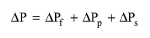
At the center of a baghouse model, is the estimation of the pressure drop across the filter as dust is being accumulated at the bags. The total pressure drop can be viewed as the sum of three terms:
|
|
eq. (A.118) |
where:
● ΔPf is the pressure drop due to the fabric
● ΔPp is the pressure drop due to the particulate layer, and
● ΔPs is the pressure drop due to the baghouse structure.
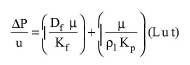
The last term is usually very low (compared to the other two) and it is neglected, whereas expressions for the other two terms can be acquired by applying Darcy’s law for fluid flow through porous media. After substitution of above terms and rearrangement we arrive at the following expression, which is known as the Drag Filter Model for Baghouse Filter Operation:
|
|
eq. (A.119) |
where:
● Df is the depth (in the direction of flow) of the filter (m)
● μ is the gaseous viscosity (kg/m-s)
● Kf is the permeability of the filter (m2)
● Kp is the permeability of the particulate layer (m2)
● ρl is the bulk density of the particulate layer (kg/m3)
● u is the linear velocity of the gas (m/s)
● L is the dust loading (kg/m3)
● t is the time the bag has been in operation since last cleaning
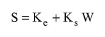
The above equation is typically expressed in the following form:
|
|
eq. (A.120) |
where S is the Filter Drag (Pa-s/m):
|
|
eq. (A.121) |
Ke is the Extrapolated Clean Cloth Filter Drag (Pa-s/m):
|
|
eq. (A.122) |
Ks is the ‘slope’ constant for the Filter Drag Model (N-s/kg-m):
|
|
eq. (A.123) |
W is the areal dust density (kg/m2 of fabric):
|
|
eq. (A.124) |
The above coefficients Ke and Ks are usually measured experimentally from pilot plant tests on dusty gas that is similar to the one for which the design is being made. Since the measurement of Ks is sensitive with respect to the linear velocity range (Ks varies in proportion to the square root of u), if possible, we should adjust the value to account for the difference between the value of linear velocity when Ks was measured and the linear velocity when the model is applied.
All baghouses are constructed with several compartments. When it is time to clean the bags, one compartment is isolated from the dusty gas flow. Then as the bags are being cleaned (either by blowing air in the opposite direction of the flow or by shaking the bags) dust falls into the hopper below the compartment and eventually it is removed. The number of compartments chosen during the design depends on the total flow to be filtered, the maximum allowable (or available) pressure drop, the filtration time (Tf) between two cleanings of the same compartment, and the time required to clean one compartment (Tc).
In Design Mode of calculation the user specifies the desired linear velocity of the gas through the filter and as design constraint the user must specify a maximum allowable number of compartments.
In summary, baghouse filter step in design mode calculates as follows:
Given
● Component Retention Coefficients
● Filter Drag Model’s Coefficients (Ke, Ks) (Set By User or Calculated)
● Bag Diameter
● Bag Length
● Cleaning Time
● Either a maximum pressure drop, or a desired filtration time
and,
● Linear Velocity
● Max Number of Compartments
● Number of Bags in Each Compartment
Calculate
● Number of Units Required
● Number Compartments in Each Unit
In Rating Mode, the user describes the dimensions of a baghouse filter and the model in return calculates the linear velocity of the gas through the filter.
In summary, a baghouse filter step set in rating mode calculates as follows:
Given
● Component Retention Coefficients
● Filter Drag Model’s Coefficients (Ke, Ks) (Set By User or Calculated)
● Bag Diameter
● Bag Length
● Cleaning Time
● Either a maximum pressure drop, or a desired filtration time
and,
● Number of Units Required
● Number Compartments in Each Unit
● Number of Bags in Each Compartment
Calculate
● Linear Velocity
1. C. David Cooper and F.C. Alley, (1990) Air Pollution Control: A Design Approach, McGraw-Hill, Inc.
The interface of this operation has the following tabs:
● Oper. Cond’s, see Baghouse Filtration: Oper. Conds Tab
● Drag, see Baghouse Filtration: Drag Tab
● Labor, etc, see Operations Dialog: Labor etc. Tab
● Description, see Operations Dialog: Description Tab
● Batch Sheet, see Operations Dialog: Batch Sheet Tab
● Scheduling, see Operations Dialog: Scheduling Tab