In gas absorption, a component from a vapor stream is transferred into a liquid stream with which it comes in contact. This operation model simulates an absorption operation in a continuous countercurrent packed tower under the assumption that the inert (i,e., design-component free) molar flows at the inlet and outlet are almost constant. If the above condition is not met, practically, if either of the inert flowrates changes more than 3% (which is an arbitrary limit), calculations will not be accurate and a relevant notification will be generated by the program.
In addition, the model can account for reactions that may take place in the liquid phase but these are assumed to be independent of absorption.
In Design Mode, the user must specify the components that are absorbed along with the desired % Absorption and the program will size the equipment based on the absorption percentage of the design component (see ‘Equipment Sizing’ below). In Rating Mode, the user can either select a design component and have its % Absorption percentage calculated by the program or set the design component to “none”. In the latter case, the % Absorption percentage of all components does not depend on the column size.
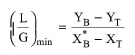
Notice that in Design Mode there is the option to auto-adjust the flowrate of the liquid stream based on the minimum liquid to gas ratio, (L/G)min, multiplied by a user-supplied operating factor. The (L/G)min which corresponds to an infinite column height is calculated by eq. (A.297) which is derived by the mass balance around the column. In practice, we are looking for the slope of the operating line that meets the equilibrium line at y = yB (the molar fraction of the design component in the gaseous inlet stream).
|
|
where, YB is the molar ratio of the design component in the gaseous inlet stream, YT is the molar ratio of the design component in the gaseous outlet stream, XT is the molar ratio of the design component in the liquid inlet stream and XB* is the molar ratio of the design component that is in equilibrium with YB.
Finally, by checking the respective option, the program can also perform reaction calculations in the liquid phase which are assumed to occur after absorption is completed.
The model will calculate the temperature of the output streams based on the energy balance dictated by the user specification. If the Assume Thermal Equilibrium option is selected the model will calculate the common temperature of the top and bottom streams. Alternatively, if the top stream temperature is provided by the user, the program will calculate the bottom stream temperature and vice versa.
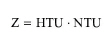
The sizing of the equipment is based on the assumption that the inert gaseous and liquid flows (i.e., the flows excluding the design component) can be considered constant throughout the column. In Design Mode, the height (Z) of the column is calculated by from the overall height of a gas-phase transfer unit (HTU) and the overall number of gas-phase transfer units (NTU):
|
|
|
|
eq. (A.299) |
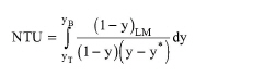
The overall number of gas-phase transfer units is defined as:
where:
● yB is the mole fraction of the design component at the bottom inlet gas stream,
● yT is the mole fraction of the design component in the top outlet gas stream,
● y* is the vapor equilibrium mole fraction of the design component,
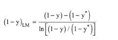
● (1-y)LM is the logarithmic mean value of 1-y and 1-y* defined as:
|
|
eq. (A.300) |
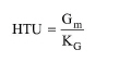
The overall height of gas-phase transfer unit is defined as:
|
|
eq. (A.301) |
where:
● Gm is the molar gas flux (mol/m2/s), and
● KG is the overall mass transfer coefficient for the gas phase (mol/m3/s).
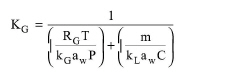
The overall mass transfer coefficient for the gas phase (KG) is given by:
|
|
eq. (A.302) |
where:
● RG is the universal gas constant (8314 J/(mol K)),
● T is an average temperature of the absorption column (K),
● P is the column’s pressure (Pa),
● kL is the mass transfer coefficient for the liquid phase (m/s),
● kG is the mass transfer coefficient for the gas phase (m/s),
● aw is the drenched pacing area (m-1),
● m is the slope of the equilibrium line, and
● C is the molar density of the liquid phase (mol/m3).
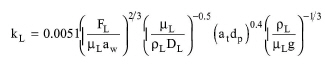
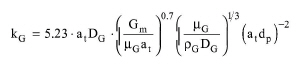
The coefficients kL and kG are calculated from the following correlations developed by Onda et al.:
|
|
eq. (A.303) |
|
|
eq. (A.304) |
where:
● dp is the nominal packing diameter (m),
● ρG is the gas phase density (kg/m3),
● DL is the liquid phase diffusivity (m2/s), and
● DG is the gas phase diffusivity (m2/s).
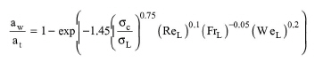
The drenched area aw is calculated from a correlation proposed by Onda et al. (1968):
|
|
eq. (A.305) |
where:
● at is the total packing surface area per packed bed volume (m-1),
● σC is the critical surface tension of packing (N/m),
● σL is the surface tension of the liquid phase (N/m),
● ReL is the dimensionless Reynolds number,
● FrL is the dimensionless Froude number, and
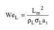
● WeL is the dimensionless Weber number.
The Reynolds number is defined as:
|
|
eq. (A.306) |
where:
● Lm is the superficial mass liquid flux (kg/m2/s), and
● μL is the liquid phase viscosity (N s/m2).
The Froude number is defined as:
|
|
eq. (A.307) |
where:
● ρL is the liquid phase density (kg/m3), and
● g is the gravity constant (9.8 m/s2).
The Weber number is defined as:
|
|
eq. (A.308) |
The Onda correlations have been verified over:
0.5 < Lm < 0.43 kg/m2-s, 0.017 < Gm < 1.7 kg/m2-s,
with packing materials ranging in nominal diameter from 10 to 55 mm.
The diameter of the packed bed as well as the pressure drop are calculated using the flooding and pressure drop correlation shown in Figure 6.34 of Treybal (1980).
1. McCabe W. L., J. C. Smith, and P. Harriott. (1993). Unit Operations of Chemical Engineering, McGraw-Hill.
2. Treybal, R.E. (1980). Mass-Transfer Operations, McGraw-Hill.
3. Onda K., H. Takeushi H., and Y. Okumoto. (1968). J. Chem. Eng. Japan, 1, 1, p. 56-62.
The interface of this operation has the following tabs:
● Oper. Cond’s, see Absorption: Oper. Conds Tab
● Reactions, see Stoichiometric Reaction/Fermentation Operation: Reactions Tab
● Packing, see Absorption: Packing Tab
● Labor, etc, see Operations Dialog: Labor etc. Tab
● Description, see Operations Dialog: Description Tab
● Batch Sheet, see Operations Dialog: Batch Sheet Tab
● Scheduling, see Operations Dialog: Scheduling Tab