This dialog is available through the Agitated Tank Operations: Vent/Emissions Tab. It allows you to choose the emission model that will be used to calculate emissions for a selected component.
The following table shows a brief description of the variables appearing in this tab. The table also displays their default values and their generally acceptable range:
|
Variable |
Default Value |
Range |
|
|
||
|
● Component Name |
None |
Any Name |
|
○ n Factor |
0.6 |
Positive |
|
○ Rl/Rt |
1.0 |
Positive |
|
○ Kga/Kla |
70.0 |
Positive |
Symbol Key: ○ User-specified value (always input); ● Calculated value (always output); ◙ Sometimes input, sometimes output
The following list describes the available specification choices in this tab; for more details on how these are implemented, see Agitated Tanks - Emission Model.
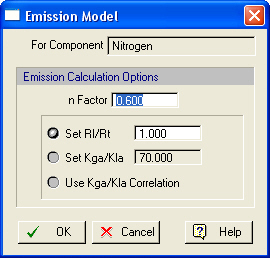
•Emission Calculation Options...
For each VOC component, you may specify the parameters that are used for the calculation of the overall mass transfer coefficient through this dialog. You may set the value of the n-factor and select one of the following calculation options:
a) Set the (Rl/Rt) ratio,
b) Set the (kga/kla) ratio, or
c) Use the (kga/kla) correlation (for mechanically aerated systems only).
Note that the third option is only available if ‘Surface Air’ is selected as the Aeration System through the ‘Oper. Cond’s’ tab of an operation. By default, SuperPro Designer uses a n-factor equal to 0.6 and a (Rl/Rt) ratio equal to one for all emitted components.