eq. (A.198)
Decanters are used to separate liquids where there is a sufficient difference in density between the liquids for the droplets to settle readily. Decanters are essentially tanks which give sufficient residence time for the droplets of the dispersed phase to rise (or settle) to the interface between the phases and coalesce. In an operating decanter there will be three distinct zones or bands: clear heavy liquid: separating dispersed liquid (the dispersion zone); and clear light liquid.
Decanters are normally designed for continuous operation, but the same design principles will apply to batch operated units. A great variety of vessel shapes are used for decanters, but for most applications a cylindrical vessel will be suitable, and will be the cheapest shape.
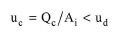
A rough estimate of the decanter volume required can be made by taking a hold-up time of 5 to 10 min, which is usually sufficient where emulsions are not likely to form (Coulson et al., 1983). The decanter vessel is sized on the principle that the velocity of the continuous phase (uc) must be less than the settling velocity of the droplets of the dispersed phase (ud). Plug flow is assumed and the velocity of the continuous phase is calculated based on the volumetric flowrate of the continuous phase (Qc) and the area of the interface (Ai) as follows:
|
|
eq. (A.198) |
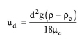
Stokes’ law is used to determine the settling velocity of the droplets:
|
|
eq. (A.199) |
where d is the droplet diameter, g is the gravitational acceleration (9.81 m/s2), ρ is the density of the dispersed phase, ρc is the density of the continuous phase, and μc is the viscosity of the continuous phase.The above equation is used to calculate the settling velocity with an assumed droplet diameter of 150 mm (the droplet diameter can be adjusted by the user), which is well below the droplet sizes normally found in decanter feeds. If the calculated settling velocity is greater than 4x10⁻³ m/s, then a figure of 4x10⁻³ m/s is used.
1. Coulson, J.M., J.F. Richardson, and R.K. Sinnott (1983). Chemical Engineering - Design, Volume 6, Pergamon, pp. 344-348.
The interface of this operation has the following tabs:
● Oper. Cond’s, see Decanting: Oper. Conds Tab
● Labor, etc, see Operations Dialog: Labor etc. Tab
● Description, see Operations Dialog: Description Tab
● Batch Sheet, see Operations Dialog: Batch Sheet Tab
● Scheduling, see Operations Dialog: Scheduling Tab