eq. (A.333)
This operation models the decrease in temperature of a continuous flow or batch stream. The heat is removed by an appropriate cooling agent that is specified by the user.
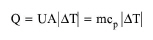
The energy balance is represented by the following equation:
|
|
eq. (A.333) |
where:
● Q is the cooling duty (kcal/h),
● U is the overall heat transfer coefficient (kcal/h-°C-m2),
● A is the heat transfer area (m2),
● ΔT is the log mean temperature difference in the system (the driving force) (°C),
● m is the mass flowrate of the stream (kg/h), and
● cp is the specific heat capacity of the stream (kcal/kg-°C).
U is always specified by the user and m and cp are always calculated based on the stream flow and composition. When the user specifies the exit temperature (equivalent to specifying the value of ΔT), the above equations are solved for Q and A. When the user specifies the value of Q, the above equations are solved for ΔT and A. If the calculated A exceeds the maximum heat transfer area, the program assumes multiple units operating in parallel with a total heat transfer area equal to the calculated.
In Rating Mode, the calculated heat transfer is compared with the specified and if it is smaller, the user is advised to increase the heat transfer area and/or the number of units.
The interface of this operation has the following tabs:
● Oper. Cond’s, see Cooling: Oper. Conds Tab
● Labor, etc, see Operations Dialog: Labor etc. Tab
● Description, see Operations Dialog: Description Tab
● Batch Sheet, see Operations Dialog: Batch Sheet Tab
● Scheduling, see Operations Dialog: Scheduling Tab